Hardware specification
Note
The following hardware specifications are provided here as a general reference; differences with the product may exist.
Scope of delivery
Standard delivery for an rc_randomdot includes the rc_randomdot projector, the mounting bracket and 4 screws, a 30 cm cable to connect the rc_randomdot to the rc_visard, and a quickstart guide.
The full manual is available in digital form at https://www.roboception.com/documentation.
The following picture shows the important parts of the rc_randomdot which are referenced later in the documentation.
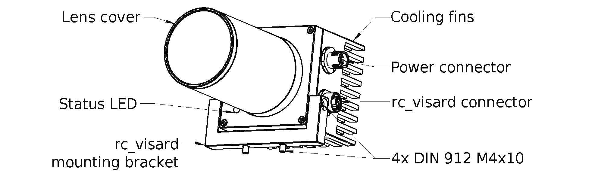
Fig. 2 Parts description
Technical specification
| rc_randomdot | |
|---|---|
| Illumination Mode | Strobe |
| Wavelength | White (5500 K) |
| Working distance | 500 mm to 3000 mm |
| Field of View | 62° x 48° (diagonal 75°) |
| Lens (C-Mount) | 1”, 12 mm, f min 1:1.4 |
| Lens Type | VS Technology VS-1214H1 |
| Power supply | 24 V (22 V to 29 V), 44 W (68 W including rc_visard) |
| Connectors | M12, 8 Pin, A-coded |
| Size (W x H x L) | 70 mm x 70 mm x 152 mm |
| Weight | ~ 660 g |
Mechanical dimensions
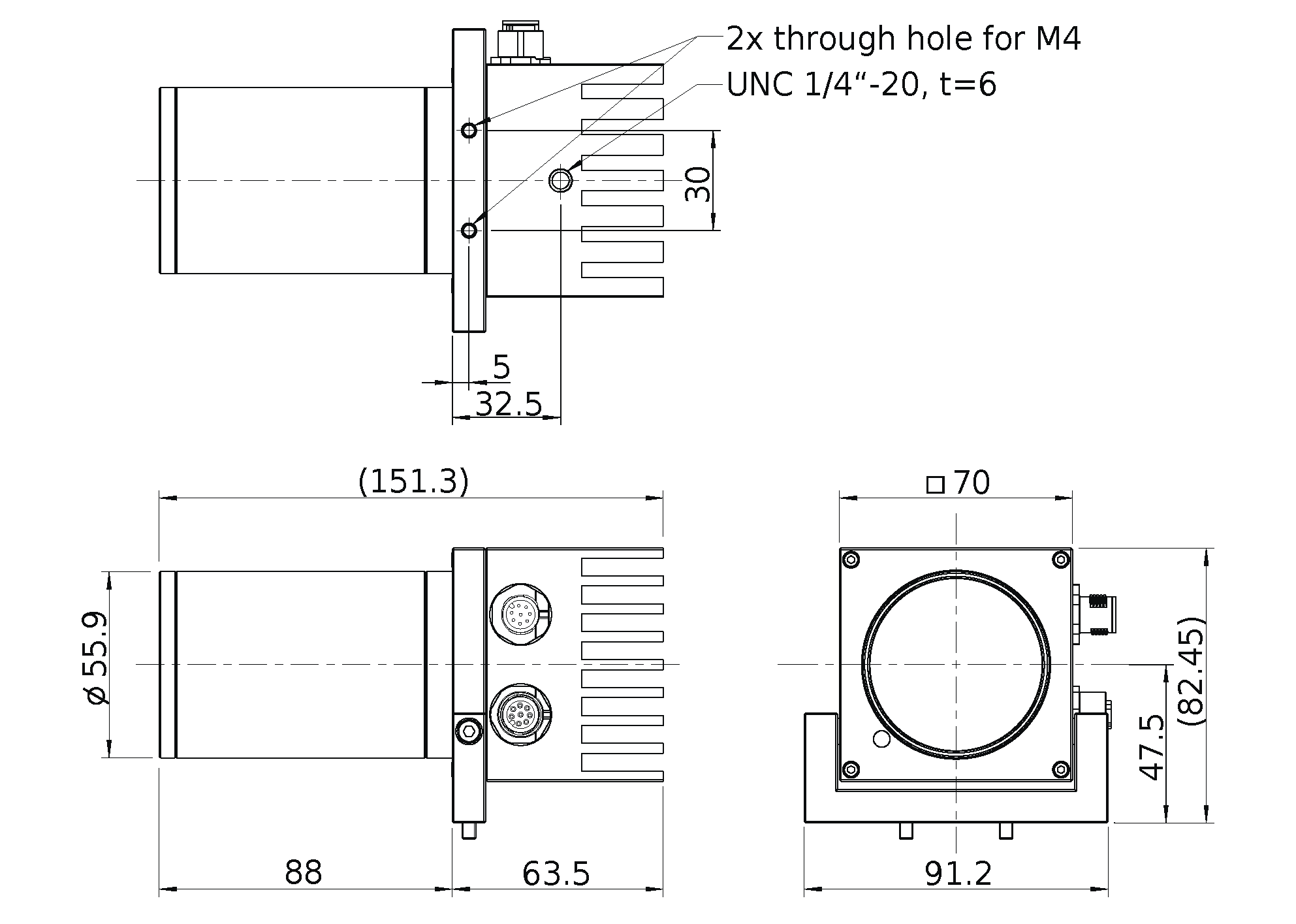
Fig. 3 Overall dimensions of the rc_randomdot White
CAD models of the rc_randomdot can be downloaded from https://www.roboception.com/download. The CAD models are provided as-is, with no guarantee of correctness.
Environmental and operating conditions
The rc_randomdot is designed for industrial applications. Always respect the storage, transport, and operating environmental conditions outlined in Table 2.
| rc_randomdot | |
|---|---|
| Storage/Transport temperature | -25 °C to 70 °C |
| Operating temperature | 0 °C to 45 °C |
| Relative humidity (non condensing) | 20 % to 80 % |
| Vibration | 2.5 g |
| Shock | 25 g |
| Protection class | IP54 |
| Others |
|
The rc_randomdot is designed for an operating temperature (surrounding environment) of 0 °C to 45 °C and relies on convective (passive) cooling. Unobstructed airflow, especially around the cooling fins, needs to be ensured during use. The rc_randomdot should only be mounted on top of the rc_visard using the provided mechanical mounting interface, and all parts of the housing must remain uncovered. A free space of at least 10 cm extending in all directions from the two devices, and sufficient air exchange with the environment is required to ensure adequate cooling. Cooling fins must be free of dirt and other contamination.
The housing temperature depends on the exposure time, exposure mode, sensor orientation, and surrounding environmental temperatures. When the projector’s power LED temperature exceeds 75°C (corresponding to a housing temperature of approximately 60°C), the LED at the front will turn red.
Power-supply specifications
The rc_randomdot needs to be supplied by a DC voltage source and will in turn power a connected rc_visard. The rc_randomdot’s standard package doesn’t include a DC power supply. The power supply contained in the connectivity kit may be used for initial setup. For permanent installation, it is the customer’s responsibility to provide suitable DC power. Each rc_randomdot and rc_visard pair must be connected to a separate power supply. Connection to domestic grid power is only allowed through a power supply according EN 62368-1.
| Min | Nominal | Max | |
|---|---|---|---|
| Supply voltage | 22.0 V | 24 V | 29.0 V |
| Max power consumption | 40 W | ||
| Max power consumption during exposure incl. rc_visard | 65 W | ||
| Overcurrent protection | Supply must be fuse-protected to a maximum of 2 A | ||
| Standards compliance | see Electronical and safety standards | ||
Warning
Exceeding maximum power rating values may lead to damage to the rc_randomdot, rc_visard, power supply, and connected equipment.
Warning
A separate power supply must power each rc_randomdot and rc_visard pair.
Warning
Connection to domestic grid power is allowed through a power supply certified according to EN 62368 and as EN55011 Class B only.
Wiring
Only a 30 cm cable connecting the rc_randomdot to the rc_visard is supplied with the standard package. It is the customer’s responsibility to obtain the proper cabling for connecting the rc_randomdot to power. A suggestion of components can be found in Accessories .
Warning
Proper cable management is mandatory. Cabling must always be secured to the rc_visard and rc_randomdot base with a strain-relief clamp so that no forces due to cable movements are exerted on the devices’ M12 connectors. In robotic applications, enough slack needs to be provided to allow for full range of movement of the rc_visard and rc_randomdot without straining the cables. The cables’ minimum bend radii need to be observed.
The rc_randomdot provides an industrial 8-pin A-coded M12 plug connector for power and GPIO connectivity and an 8-pin A-coded M12 socket connector for connectivity to the rc_visard. Both connectors are located on the left side of the rc_randomdot as indicated in Fig. 2. Type and orientation of the connectors is shown in Fig. 4.
Connectors are rotated so that standard 90° angled connectors will exit horizontally, towards the back of the projector.
The power supply must be connected to the top (plug) M12 connector of the rc_randomdot. Make sure to check the polarity of your power supply as reverse polarity will damage the rc_randomdot. The bottom (socket) M12 connector is connected to the bottom M12 connector of the rc_visard with the supplied 30 cm M12 shielded cable.
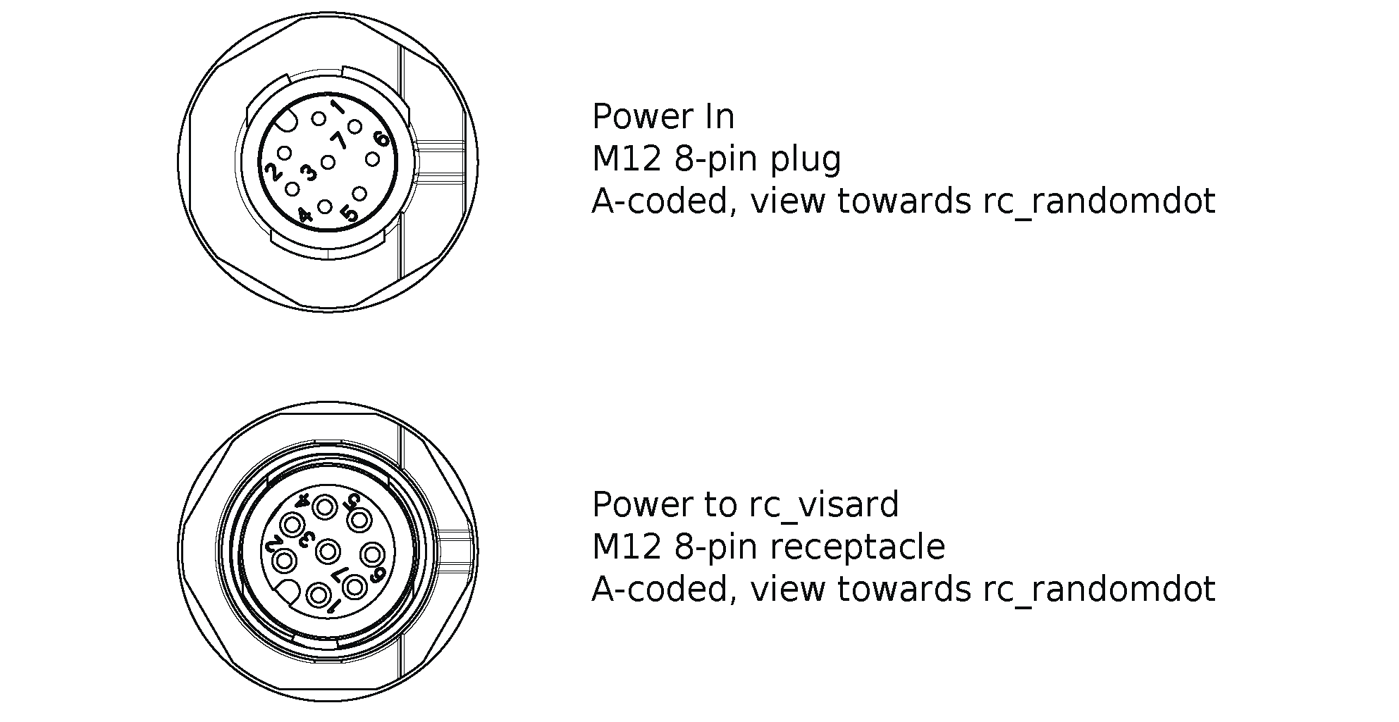
Fig. 4 Pin positions for Power IN/GPIO (top) and rc_visard (bottom) connector
Pin assignments for the Power IN connector are given in Table 4.
| Pin | Assignment | Reference |
|---|---|---|
| 1 | N/C | / |
| 2 | +24 V Power IN | GND |
| 3 | GPIO In 1 Robot | GPIO GND |
| 4 | GPIO GND | GPIO GND |
| 5 | GPIO Vcc | chassis GND |
| 6 | GPIO Out 1 Robot (image exposure) | chassis GND |
| 7 | GND | GND |
| 8 | GPIO Out 2 | chassis GND |
Pin assignments for the rc_visard connector are given in Table 5.
| Pin | Assignment | Reference |
|---|---|---|
| 1 | GPIO Out 2 (Overtemp): 1 = OK (24 V), 0 = !OK (0 V) | chassis GND |
| 2 | +24 V Power OUT | GND |
| 3 | GPIO Out 1 | chassis GND |
| 4 | GND (GPIO GND) | GND |
| 5 | +24 V (GPIO Vcc) | GND |
| 6 | GPIO In 1 (Light Trigger) | GND |
| 7 | GND | GND |
| 8 | GPIO In 2 | GND |
All GPIOs are decoupled by photocoupler. GPIO In 1 needs to be connected to the rc_visard GPIO Out 1 signal, which can be set to provide an exposure sync signal using the rc_visard’s IOControl module. A logic high level of the rc_visard’s GPIO Out 1 signal triggers the projector light. The projector is ON as long as GPIO In 1 is HIGH.
GPIO Out 2 of the projector provides a ‘projector present’ signal that is high when an rc_randomdot projector is connected to the rc_visard and operating normally. The signal will transition to low during fault (overtemperature) conditions. The status of the rc_visard GPIOs is available in every image via the GigE Vision “Chunk Data”. For more details, please refer to https://doc.rc-visard.com/latest/en/gigevision.html#chunk-data.
Note
- The state of the rc_randomdot GPIO In 1 is mirrored to GPIO Out 1 Robot
- The state of the rc_randomdot GPIO In 2 is mirrored to GPIO Out 2 Robot
- The state of the rc_randomdot GPIO In 1 Robot is mirrored to GPIO Out 1
Pins of unused GPIOs should be left floating.
GPIO circuitry and specifications are shown in Fig. 5. The maximum rated voltage for GPIO In and GPIO Vcc is 29 V.
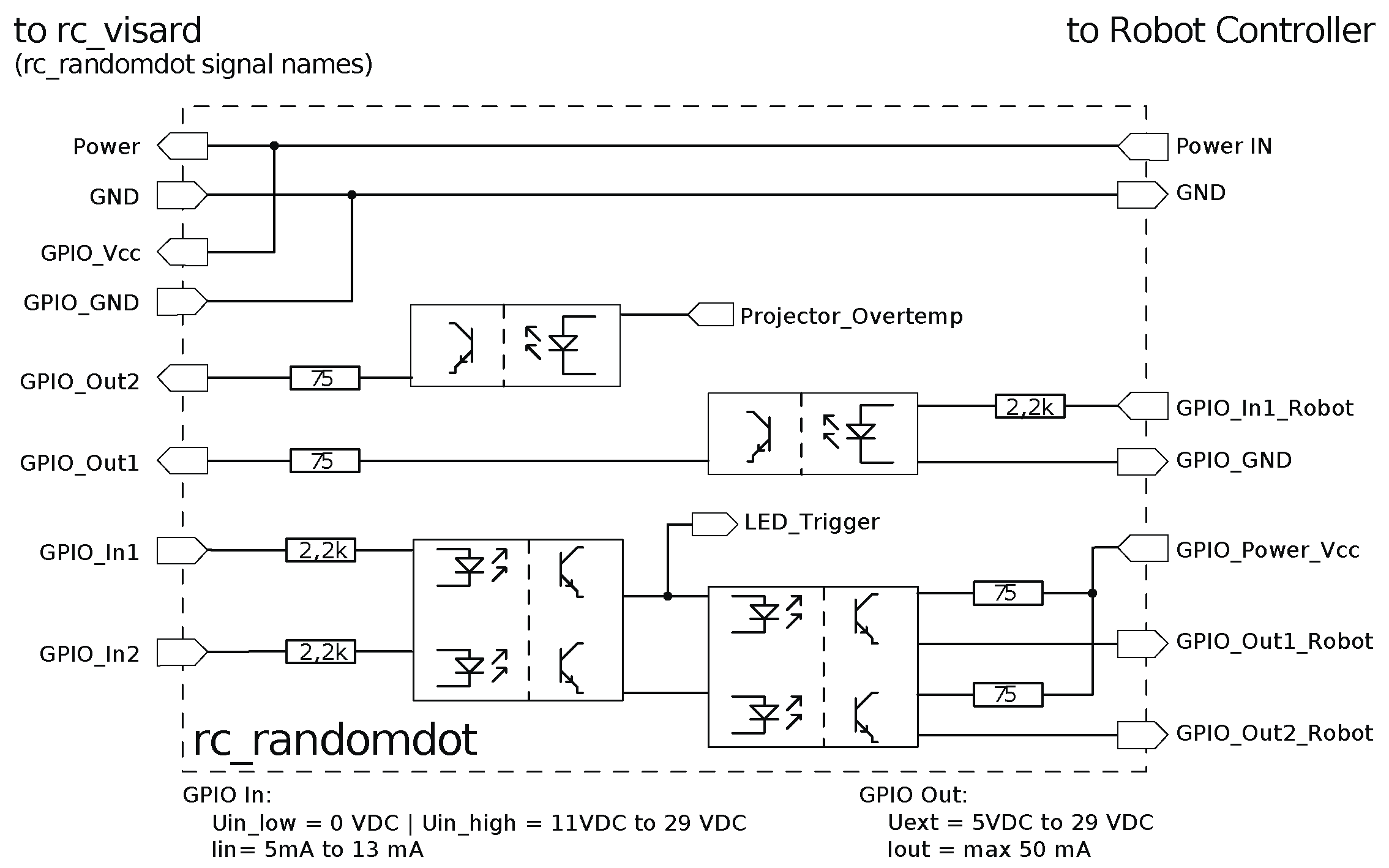
Fig. 5 GPIO circuitry and specifications – do not connect signals higher than 29 V
Warning
Do not connect signals with voltages higher than 29 V to the rc_randomdot.
Electrical properties
The power LED driver inside the rc_randomdot is set to automatically pulse the LED according to the state of the GPIO In 1 trigger pin.
For a short trigger pulse (< 25 ms), the projector is driven at maximum power (projector LED maximum current of 2,2 A). If the pulse is longer, the driver automatically decreases projector LED current to 0,4 A (18% of max current) to protect the projector LED against damage.
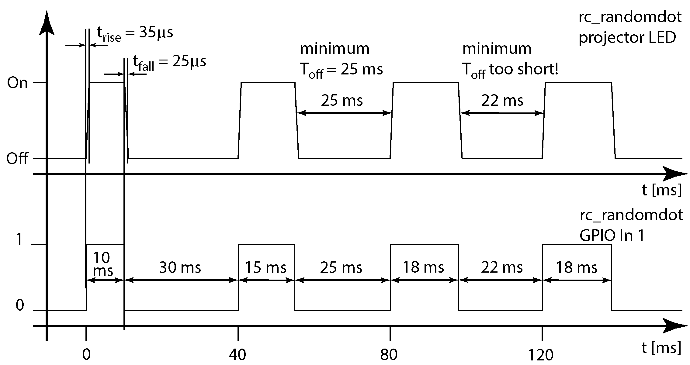
Fig. 6 Timing of the projector LED with respect to the rc_randomdot GPIO In 1 pin
Fig. 6 shows the timing properties of the rc_randomdot projector LED with respect to the rc_randomdot’s GPIO In 1. Please note that the rc_randomdot must be turned off for a minimum of 25 ms between light pulses. This limits the maximum allowed exposure time of the connected rc_visard to 15 ms in ExposureActive mode to prevent overheating of the rc_randomdot. It is the user’s responsibility to limit the exposure time of the rc_visard accordingly. In ExposureAlternateActive mode, the full 18 ms exposure time of the rc_visard may be used as only every second exposure triggers the rc_randomdot.
For an in depth description of rc_visard projector control settings and operating modes, please refer to the IO and Projector Control section in the full rc_visard documentation at https://doc.rc-visard.com/latest/en/iocontrol.html .
Warning
In ExposureActive mode, the exposure time of the rc_visard must be limited to a maximum of 15 ms to prevent overheating of the rc_randomdot. It is the user’s responsibility to ensure this setting.
| Status LED color | rc_randomdot |
|---|---|
| Red | Overtemperature warning projector LED temperature > 75 °C |
| Green | Power ON |
| Blue | Trigger Signal active, projector LED ON |
Optical properties
The rc_randomdot projects a rectangular pattern of semirandom dots with 50% density. Optimal working distance is between 500 mm and 3 m. Focus and the aperture can be adjusted with manual settings of the C-mount lens.

Fig. 7 Projected pattern of semirandom dots with 50% density
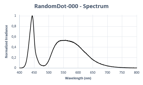
Fig. 8 Emission spectrum of the rc_randomdot White