Installation
Warning
The instructions on Safety related to the rc_randomdot and rc_visard must be read and understood prior to installation.
Mounting
The rc_randomdot offers a mounting-point setup with standard tripod thread at the bottom, and pivot points for the provided mounting bracket on either side.
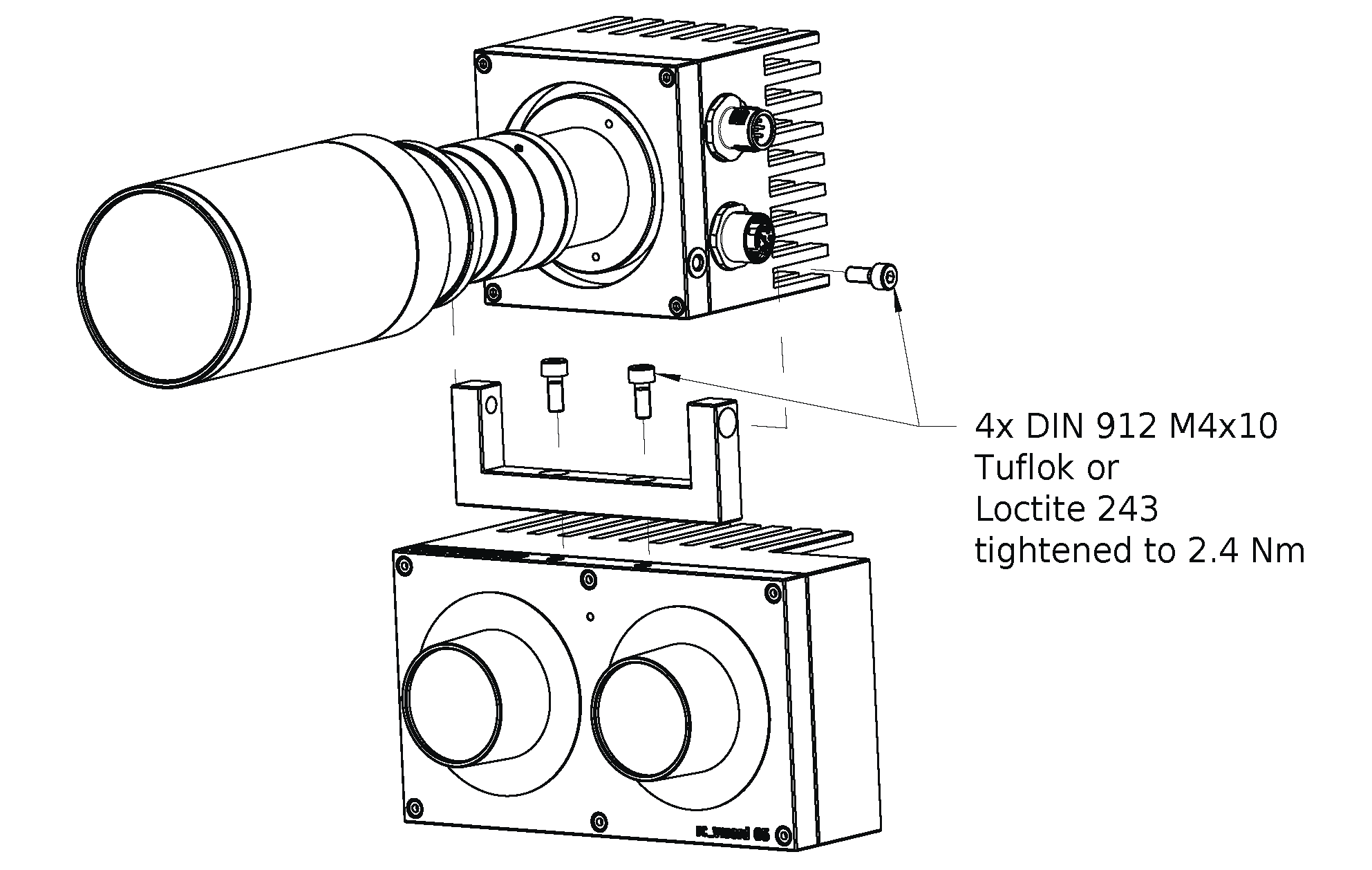
Fig. 9 Mounting bracket for connecting the rc_randomdot to the rc_visard
For troubleshooting purposes, the projector may be mounted using the standardized tripod thread (UNC 1/4”-20) at the bottom of the housing. For mounting the rc_randomdot on top of an rc_visard in static or low dynamic applications (e.g. above robot cells or on mobile platforms), the supplied mounting bracket must be attached to the rc_visard with two M4 x 10 8.8 machine screws, and the projector must be attached to the mounting bracket with two M4 x 10 8.8 machine screws at the pivot points. All screws must be tightened to 2.4 Nm and only TufLok nylon coated screws may be used. Alternatively screws need to be secured with a medium-strength threadlocking adhesive such as Loctite 243. Maximum thread depth is 6 mm. The supplied mounting bracket is not suitable for dynamic robot applications. It is the customer’s responsibility to provide adequate mounting of the rc_randomdot.
Warning
For permanent installations, the rc_randomdot must be mounted with four M4 x 10 8.8 machine screws tightened to 2.4 Nm torque. Screws must be Tuflok coated or secured with threadlocking adhesive. Do not use high-strength bolts.
Warning
The supplied mounting bracket is not suitable for dynamic robot applications. It is the customer’s responsibility to provide adequate mounting of the rc_randomdot.
Depending on the working distance, it might be necessary to tilt the projector downwards to cover the complete filed of view of the rc_visard. This can be accomplished by loosening the screws attaching the rc_randomdot to the mounting bracket at the pivot point, and moving the rc_randomdot to the desired angle.
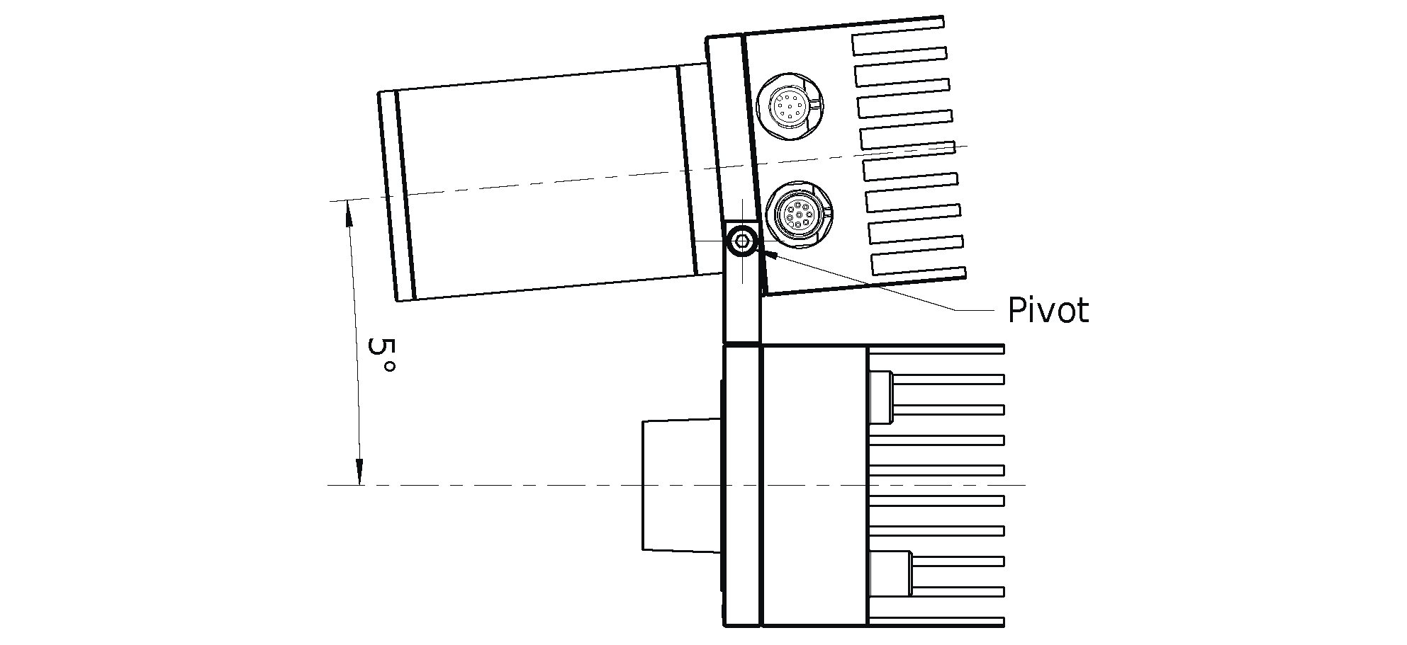
Fig. 10 Setting the desired tilt angle between rc_randomdot and rc_visard
Power-up
Note
Always fully connect and tighten all M12 connectors on the both the rc_visard and rc_randomdot before turning on the power supply.
After connecting the system to power, the LEDs on the front of the rc_randomdot and rc_visard should immediately illuminate. During the rc_visard’s boot process, it’s LED will change color and will eventually turn green. This signals that all processes are up and running. The rc_randomdot’s status LED should turn green right away. The rc_randomdot projector will flash a number of times during the boot process.
Warning
Do not look into the lens of the rc_randomdot or into the light beam at any point during startup or operation.
For troubleshooting the rc_visard’s boot process and connections, please refer to the rc_visard documentation at https://doc.rc-visard.com/latest/en/troubleshooting.html#led-colors.
Operating the projector
The rc_randomdot projector is controlled via the GPIO Out 1 of the rc_visard.
For a tutorial on operating the projector, please refer to: https://tutorials.roboception.de/rc_visard_general/projector.html.
Note
A valid IOControl license is required on the rc_visard. It is included in the standard on-board software package of all rc_visards purchased 07/2020 and thereafter. For upgrading an older rc_visard, please obtain your license at https://roboception.com/product/rc_reason-iocontrol.
State and behavior of the rc_visard’s GPIOs can then be controlled via the rc_visard’s WebGUI IOControl panel from the Modules tab. Starting with rc_visard firmware 20.10, GPIO Out 1 is set to Low by default, turning the projector off. ExposureActive turns on the rc_randomdot for exactly the exposure time of every image. High will turn the projector on continuously, but reduce power to 18% to protect the light source.
Typically, the user will select ExposureAlternateActive mode, in which the rc_randomdot is on only for the exposure time of every second image. Images with projected pattern are used for computing depth images. Images without pattern can be used for texture or other image processing modules.
In ExposureAlternateActive mode, the rc_visard’s auto exposure algorithm ensures that images with pattern are correctly exposed in order to produce dense disparity images. As identical exposure settings are used for the images without pattern, which are displayed in the WebGUI, those might be underexposed depending on overall illumination conditions. This effect can be minimized by properly adjusting environmental light conditions, projector lens aperture, and exposure time.
Adjusting focus
During production, the focus of the rc_randomdot is set to a distance 1.2 m by default. When the projector is used for a very different working distance, adapting the focus might be necessary. Perfectly focusing the projector is not crucial. A slightly blurred projection pattern will not degrade the depth image.
To inspect the sharpness of the projector pattern, the projector should be turned on permanently
by setting the Out1 / Projector mode to High on the Web GUI under
or .
The projector focus only needs to be adjusted when the projector pattern is strongly blurred. In this case, remove the rc_randomdot’s protective lens cap by unscrewing it. Then loosen the three small fixing Phillips screws on the focus ring as shown in Fig. 11. Then, turn the focus ring until the visible projector pattern becomes sharp. After that, lightly tighten the focus ring screws again and replace the protective lens cap to restore the IP54 rating and EMC compatibility of the projector.
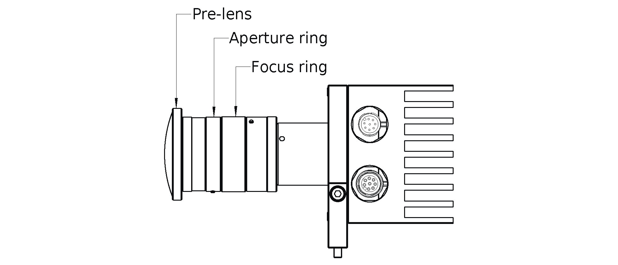
Fig. 11 Focus and aperture ring on the rc_randomdot White
Adjusting aperture
The aperture of the rc_randomdot influences the brightness of the projector pattern. By default, the aperture of the rc_randomdot is fully open, which means the projector has maximum brightness. The aperture should be adjusted so that the brightness difference between images taken with projector and images taken without projector is not too large, but the projector pattern is still visible in the images taken with projector. To find the correct setting, make sure the external light in the working environment is similar to what is expected during productive mode and the camera with the rc_randomdot is mounted at the desired distance from the scene.
Then, on the Web GUI under , set the
Exposure mode to Auto and set the Auto Exposure Mode to AdaptiveOut1.
Also set the Out1 / Projector mode to ExposureAlternateActive under IOControl Settings,
so that every second image is taken with projector pattern.
Now, the text line under the live images shows the Out1 reduction value in percent.
The Out1 reduction value describes the reduction of the brightness of the image without projection compared to the image with projection. The value should be between 10% and 20%. A higher Out1 reduction value means, that the projector is too bright compared to the external lighting, which leads to images without projector patterns being too dark. Thus, external lighting should be increased, e.g. by installing an additional light source, or the brightness of the projector should be reduced by slightly closing the aperture. In analogy, if the Out1 reduction value is too low, the projector is not bright enough compared to the external light, which means that the projector pattern will hardly be visible in the camera images and cannot enhance the depth computation. So the external light should be reduced or the projector brightness must be increased by opening the aperture.
The aperture of the projector can be adjusted by removing the rc_randomdot’s protective lens cap by unscrewing it. Then loosen the three small fixing Phillips screws on the aperture ring as shown in Fig. 11. Now turn the ring until the Out1 reduction value is in the range between 10% and 20%.
After that, the darkest object that is possible in the application should be placed in the field of view of the camera. If the dark object is not properly visible in the depth image, then the projector brightness must be increased, despite high Out1 reduction values.
In the end, lightly tighten the aperture ring screws again and replace the protective lens cap to restore the IP54 rating and EMC compatibility of the projector.